Loading...
Design guidelines

Design guidelines for 3D printed SLM metal components

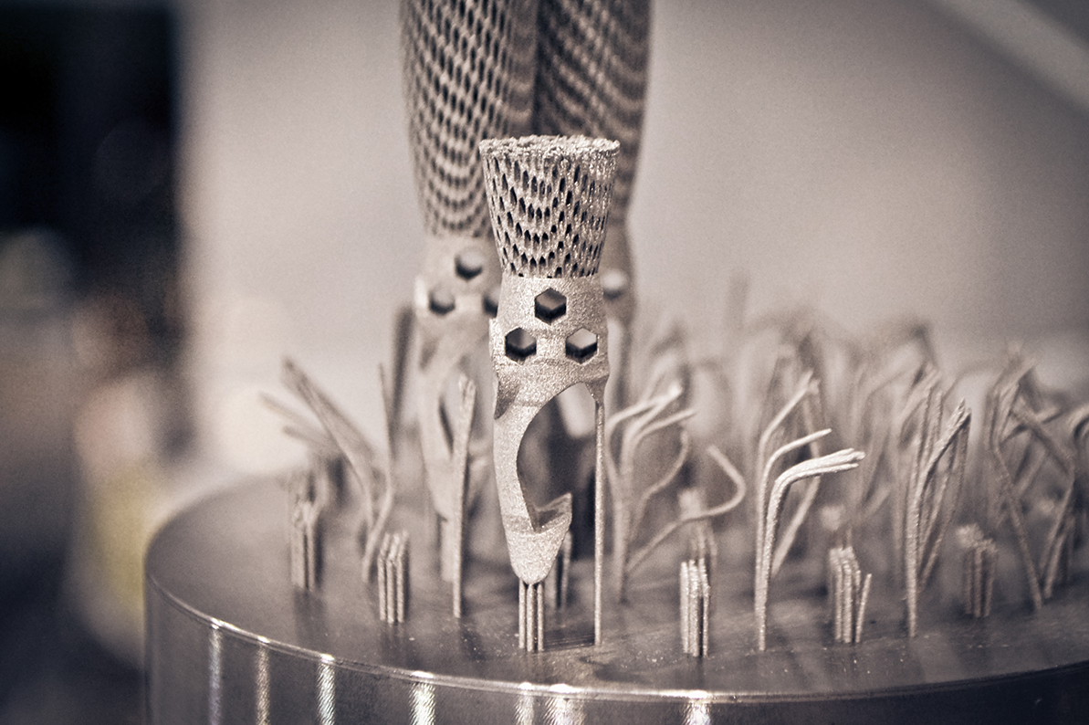
3D-Druck Bauteil SLM Metall mit Stützstrukturen

3D metal printing has become an important branch of additive manufacturing. In particular, laser melting of metal using the SLM process enables the fast, economical production of components made of aluminum, stainless steel, tool steel, Inconel, titanium, copper and many other metallic materials. Below, you will learn what to consider during the design process.

Content:

  • Basics for SLM metal printing
  • Angle
  • Support structures
  • Thermal stress and shrinkage
  • Tolerances
  • Summary
  • Notes for the order


In selective laser melting (SLM), the powdery, metallic starting material is melted at the processing points by the thermal energy of a high-power laser. Layer by layer, components are created that retain the specific properties of the starting material to the greatest possible extent, offer a density of 99.9% and are characterized by exceptional strength.

A unique, fine microstructure of the 3D-printed metal workpieces and excellent mechanical properties are characteristic of SLM 3D printing. In order for the parts to be a complete success, there are some guidelines to follow during the design process.


Fully exploit the advantages of SLM with the perfect design

Selective laser melting offers numerous advantages in the processing of metals, which can be fully exploited through adapted design. In particular, the production of internal, complex contours - for example, internal cooling channels - or the combination of assemblies to form a component is only made possible by 3D printing and cannot be realized with conventional machining strategies for milling or turning.

In lightweight construction, for applications in aerospace or the automotive industry, SLM brings not only a significant reduction in weight but also improved functionality of the products. In particular, "organic" structures modeled on nature enable completely new design approaches. In addition, the components can be produced quickly, directly from the CAD model and can be easily adapted or modified at any time

Basic design guidelines for 3D metal printing

For you to benefit from the increased value created by 3D printing, one thing is essential to internalize: The design of components must not be based on subtractive, conventional manufacturing! Rather, the focus must be on the design for additive manufacturing!

Prefer topologically optimized shapes or free-form surfaces and avoid converging design, straight corners and flat overhangs. Rather, focus on arcs, fillets and chamfers, and divergent design. By avoiding large surface changes between layers, you support profitable, rapid additive manufacturing right from the design stage. Always remember: by reducing the area, you reduce the volume of the body to be printed! The focus of your design must be on the functionality of the part - and should not depend on manufacturability, as is often the case with conventional manufacturing.

The flatter the angle, the poorer the surface quality

With 3D metal printing, the angles of the components must be given special consideration during design. If the angles constructed are too flat at less than 45° - resulting in downward facing surfaces - the molten layer sags through the loose powder underneath. This leads to the formation of slag and significantly impairs surface quality.

Furthermore, flat angles require the use of support structures. Supported surfaces are always of poorer quality for printing reasons and should be avoided as far as possible for high surface qualities. Therefore, design your components with steep angles greater than 45° to avoid slag formation and to get by with as few support structures as possible.

Support structures: welcome and not welcome

Support structures, also known as supports, put designers in a real quandary when designing components to be printed. On the one hand, support structures prevent the deformation of the components during 3D printing and minimize the shrink line; on the other hand, the surface quality of the components suffers on the surfaces to which support structures are attached. Last but not least, support structures inevitably lead to reworking - because the supports have to be removed after printing.

To ensure the generally high quality of your components, the fewer support structures, the better. What exactly can be built without support structures also always depends on the material:

SLM Metall 3D-Druck Grafik Konstruktion

For steel, stainless steel, Inconel:

  • Large surfaces: α > 60°
  • Medium surfaces: α > 50 - 55°
  • Small surfaces: α > 45°

For titanium, aluminum:

  • Large surfaces: α > 60°
  • Medium surfaces: α > 50 - 55°
  • Small surfaces: α > 45°

In general, if you want to print without support structures as much as possible, the following guidelines should be followed in the design:

SLM Metall 3D-Druck Grafik Konstruktion
  • Horizontal circular holes can be printed without support structures when the inner diameter is smaller than 8mm
  • Horizontal bridges can be printed at L smaller than 1.2 mm without support structures
  • Horizontal downward facing flanges can be printed without support structures at L smaller than 0.75mm

In many cases, you can avoid support structures with an adapted design. Do without downward-facing surfaces in the design. In this way, you can achieve a self-supporting geometry. When designing, always ask yourself where support is needed and whether this support can be removed after 3D printing! If you use free-form structures, less support structure is generally needed. With soft transitions through the use of radii, etc., you also create a better quality of the components.

Thermal stress, shrinkage and the effect on quality

Selective laser melting sometimes produces immensely high melting temperatures, which are 1650° C for titanium and still 1200° C for stainless steel. In combination with fast cooling rates (less than 1ms for - 100° C), material-specific stresses occur in the material. The stresses accumulate over all printed layers, since with each printing process the underlying layers are also heated and cooled again. The negative thermal influences can be mitigated directly in the design:

  • Reduce the area to be melted per layer.
  • Make sure that the longest part of the expansion of the components is in the Z axis
  • With a good heat transfer to the base plate you will achieve an optimal heat distribution

If the orientation in the build space is important for your project, make an "individual request" and include this information. The print partner will take this into account during production.

If thermal stresses cannot be avoided, remedial action is taken with design measures. Support structures are often used to compensate for thermal stresses in order to keep the component in shape. However, with this procedure, the stresses remain in the component - if the support structure is removed, the component warps. This can be remedied by heat treatment while the component is still on the building platform. This is implemented accordingly by the print partner.

SLM Metall 3D-Druck Grafik Konstruktion

Also be sure to pay attention to the shrinkage lines during design. You can counteract unwanted shrinkage of the components with simple adjustments to the design. See sketch: Avoid the shape on the left in the picture, if the shape is necessary, then work with curves (center picture), or turn the shape "upside down" for printing (right side of the picture).

Tolerance values in 3D metal printing

In 3D metal printing, the tolerances do not correspond to conventional manufacturing. Possible tolerances in SLM are assigned to class "M" according to ISO 2768. Depending on the shape and contour, the tolerances can deviate even further and lie in the range of ± 0.4% or even ± 0.3%. For very exact component sides, it may therefore be necessary to refine with post-processing, for example by milling.

Summary design guidelines for SLM metal parts:

Do

  • Increase added value
  • Focus on functionality
  • Additive design, topologically optimized with freeform surfaces, diverging
  • α > 45°
  • Apply arcs, fillets and chamfers
  • Reduce areas to reduce volume
  • Avoid too large surface changes between layers
  • When designing, define the orientation of the structure first, as this has an influence on the rest of the process

Don't

  • Design for subtractive, conventional manufacturing
  • α < 45°
  • converging design
  • Straight corners, flat overhang
  • High number of cuts
  • Focus on manufacturability

Instructions for ordering your components from Jellypipe

We will be happy to provide you with customized printing of metal components. It is important that we receive all important information so that the Print Factory can produce the component according to your wishes. The 3D print file is crucial for the production. If the print file does not contain all the instructions, or if it is a complex project, please enter an "individual request". Please give us all the important details about your design in the request.

You are also welcome to provide us with information on the alignment of the component in the installation space, desired reworking or places where tolerances must be adhered to very precisely.

If you have any further questions, please do not hesitate to contact one of our Solution Partners.

We are already looking forward to your inquiry!


Your Jellypipe

Autor

Markus Grimm
Chief Virtual Printfactory

Newsletter subscription

Stay up to date with our newsletter.